The Mustang Forum for Track & Racing Enthusiasts

Taking your Mustang to an open track/HPDE event for the first time? Do you race competitively? This forum is for you! Log in to remove most ads.

  • Welcome to the Ford Mustang forum built for owners of the Mustang GT350, BOSS 302, GT500, and all other S550, S197, SN95, Fox Body and older Mustangs set up for open track days, road racing, and/or autocross. Join our forum, interact with others, share your build, and help us strengthen this community!

ABS

This site may earn a commission from merchant affiliate links, including eBay, Amazon, and others.

598
536
I have all the pieces now and believe I have the vast majority of the wiring figured out. In the post you made what is the RNC that you referenced?
The RCM "Restraint control module" is used as the brake switch in the 2011+ mustangs, it would control the seat belts; air bags alll the safety stuff.
 
5
0
Exp. Type
HPDE
Exp. Level
3-5 Years
Los Angeles, California
The RCM "Restraint control module" is used as the brake switch in the 2011+ mustangs, it would control the seat belts; air bags alll the safety stuff.
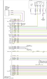
Thanks for replying. I guess I wasn't able to see the brake position switch in the wiring diagrams I came across the pin out from the screenshot in this thread. Do you happen to know where I could get the wire diagram to figure which pin is for the brake switch?
 
5
0
Exp. Type
HPDE
Exp. Level
3-5 Years
Los Angeles, California
That does help for the network connections, which I'll be hooking up so Abs and rcm can communicate via can.

What I'm still not able to figure out is which module in the 2011+ receives the mechanical brake signal and converts it to can bus so the abs can receive it. If it's rcm like tri-bar mentioned I should be in good shape as long as I know what pin receives the brake signal.

I've seen a diagram that might lead to the body control module which might make things more complicated.

Background. I have a 95 mustang with a new pro-m ecu. The pro-m has canbus, but I am unsure if it broadcasts a brake signalom the network or how to check if it does.

Thanks for the help so far everyone. This thread has been great.
 

Dave_W

Cones - not just for ice cream
1,000
1,304
Exp. Type
Autocross
Exp. Level
20+ Years
Connecticut
5
0
Exp. Type
HPDE
Exp. Level
3-5 Years
Los Angeles, California
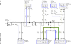
Looks like on the 2011, the parking brake switch goes to pin 1 on the Smart Junction Box (page 3 of the Vehicle Dynamic Systems diagram), which connects to CAN on pins 36 & 37 (page 4 of same).
Yes, I see that. Although that is the parking brake and I believe what I need is the brake pedal switch or the Brake On/Off (BOO).
 
5
0
Exp. Type
HPDE
Exp. Level
3-5 Years
Los Angeles, California
I just came across this and seems like it's showing up in the PCM wiring diagram as the

If that's the case than my best bet is that the pro-m pcm broadcasts the brake signal. If it doesn't I might be SOL. Worth a try maybe.

Screenshot_20230914_214837_Chrome.jpg
 

Fabman

Dances with Racecars
6,551
8,203
Exp. Type
W2W Racing
Exp. Level
20+ Years
Pleasanton: 1/2 way between Sonoma and Laguna Seca
Jesus I’m gonna have to hire somebody to wire this thing for me….
 

Dave_W

Cones - not just for ice cream
1,000
1,304
Exp. Type
Autocross
Exp. Level
20+ Years
Connecticut
I believe what I need is the brake pedal switch or the Brake On/Off (BOO).
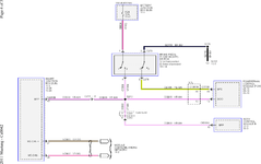
Sorry, long day and brain is frazzled. Page 4 has the diagram for the brake switch.

Note the brake switch is a DPDT switch, with one pole (pins 2 & 3 of brake switch) wired to ground pin 46 (BPS) of the PCM with brakes off, and the other pole (pins 1 & 4 of brake switch) wired to connect "hot at all times" from the Battery Junction Box to pin 13 (BOO) of the PCM, pin 19 (BPP) of the BCM, and pin 40 (BPP) of the Smart Junction Box when brakes are on. The SJB is also shown connecting to CAN in that diagram, which is really just the brake switch connections, so I think that implies it's the SJB that converts the brake switch signal to CAN.
1694755473308.png
 
598
536
There is no use of a brake switch in the 11+ ABS system. On the 05-10 system Ford used a brake switch. The RCM is the brake switch on the 11+ cars. don't mix them up or they won't work The CAM bus is not needed for it work as well. The RCM can bus only talks to the ABS pump that's how it knows your braking. The standard Can Bus can be wired in as a stand alone DO NOT tie it in with the ECU can bus. Any time you flash your ECU, it will fail. At least id did on my car. I never put the resistor in the the ABS can bus so maybe that's why. Truth is it's just not needed. When you bleed your brakes, zip up the street fast enough to engage the ABS, let is cycle and them bleed again, done.
 
Last edited:
1
0
Exp. Type
Autocross
Exp. Level
3-5 Years
Claremont
Disclaimer: This info is only for Race cars with standalone ECU setup. Ford's or otherwise.
ABS is installed and working. It turned out to be a lot easier than I expected. First it does work as a standalone system as long as you have a CAN bus. I do have it tied into the CAN bus from the ECU/OBD2. The Restraint Control Module also has it's own CAN bus that talks to the ABS unit. No brake switch to the ECU is used on the 2011-2014 systems. You can upgrade if you have the older systems. All you have to have is the 2011-2014 ABS pump/unit, RCM, ABS plug or harness. Junk yard for the harness and wires. I de-loomed the whole ABS harness and wheel sensors from my car and used them. That was the only factory wiring I used. The PDF's color codes are different on some of the wires than the Fords wiring diagrams just FYI.
The Four wheel speed sensors, a 40amp HAAT power lead, a 30amp HAAT power lead. a 5amp On/Reset switched power lead. Can bus +/- leads, RMC Can bus +/- leads to the ABS unit and two grounds. The RNC only needs ONE 10amp Power lead and the RCM CAN bus and the OBD2 CAN bus to work. All the other wires to the RCM can be removed. Between using the Ford Wiring Diagram and the Boss302R/S PDF's for the ABS harnesses it turned out to be real easy. Just time consuming because of all the splicing to route the wires the way I wanted them, but once its in, it worked.

View attachment 67462

View attachment 67463
Could you use the it without the rcm? I’m using a haltech ecu. I’d like to get the CAN systems to communicate.
 
Great thread, I sent you a private message (Tri-bar)
On the 05-09 does the ABS require the brake switch? If so which one (upper ot lower). I to have completely removed interior and alot of wiring. Car setup for SCCA CP class. First test day i did abs appeared to be working. During the event the wires for the clutch and brake switches got caught up in the steering shaft and broke the upper brake switch so i just removed all the switches. Next event had brakes locking up. AUTEL scan tool shows no abs faults or errors. When running abs bleed test every thing seams to function correctly. RCM is removed.
 
This is awesome, thanks for sharing this! It actually looks a lot simpler than I thought.

I am currently running:
  • The control pack and the Gen3 PCM to run a Gen3 Engine in my S197.
  • Stock gen1 body harness to use lights, doors, etc. Including fuse box but without the PCM.
  • RaceCapture data system that tabs into and reads the can bus and OBD2.
It is a lot of wires right now but I am looking to maintain proper functionality first before cutting into things. I am looking to trim and simplify things once everything is in working order.

My question:
Would it be enough to leave the the stock (gen1) wiring harness intact and simply swap in the Can ports from the control pack (gen3)?

This would assure intact wheel speed sensor wires, grounds and fuses without cutting into the harness more then necessary. By any chance, do you know what kind of Can info the ABS is looking for?
Optionally I could still run the gen1 ECU as a backup for such systems. Not sure though how much it does without the engine harness hooked up.
I have a 2015 mustang gt with the gen 3 swap. I have fallen to the same problem. Please help.
 

TMO Supporting Vendors

Latest posts

Buy TMO Apparel

Buy TMO Apparel
Top