The Mustang Forum for Track & Racing Enthusiasts

Taking your Mustang to an open track/HPDE event for the first time? Do you race competitively? This forum is for you! Log in to remove most ads.

  • Welcome to the Ford Mustang forum built for owners of the Mustang GT350, BOSS 302, GT500, and all other S550, S197, SN95, Fox Body and older Mustangs set up for open track days, road racing, and/or autocross. Join our forum, interact with others, share your build, and help us strengthen this community!

Adding a fuel cell. Need help with the fuel gauge.

This site may earn a commission from merchant affiliate links, including eBay, Amazon, and others.

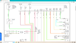
Hey all. Hopefully a quick question here. I recently bought a 2006 GT cone crusher and I turning it into a track car. It came with a 4 gallon cell but I upgraded to a 10 gallon. The new cell has a fuel level sensor and I want to hook up to the fuel gauge in the cluster. I also bought a MeterMatch from Tanks to calibrate the two to show correct levels. Now my question.... On the back of the cluster, what color is the wire that sends the signal to the gauge? I found this schematic, but I suck at this ( should have paid attention in school ). Is it the Green wire at pin18?? HELP!!!! LOL
fuel schmatic 2.png
 
With MeterMatch it doesn't care. It changes the signal for the gauge. I just need to know the factory signal wire and I can interrupt it with MeterMatch.

Sorry for the long video but you need only watch the first bit.

Thanks
 
I don't think you be able to use the cluster gauge unless you add a second fuel level sensor.

The stock system use 2 level sensors. One in each saddle of the stock tank.
Then the cluster average the 2 reading to display the remaining fuel.

You have fuel level 1 with pin 15 and 16 and fuel level 2 with pin 18 and 19.

Each sensor has 2 wires. One of those wire will have a constant voltage (Usually 5VDC).
Then the other wire will have a smaller voltage that will vary based on how much fuel you have and that's what the computer is reading.

You better off installing an external gauge if you want to see your fuel level. That's going to be much easier to install.
 

Dave_W

Cones - not just for ice cream
1,002
1,307
Exp. Type
Autocross
Exp. Level
20+ Years
Connecticut
The stock system use 2 level sensors. One in each saddle of the stock tank.
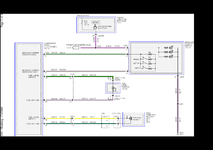
Is that for all models/engines? I don't have direct experience, but reading the wiring diagram that was posted, the "Fuel Level Input 2" circuit goes through connectors (C434) that are only labelled with "5.4L" while the "Fuel Level Input 1" circuit connectors are labelled for "5.4L" and "3.7L / 5.0L". So in my reading of the diagram, only the 5.4L-engined cars use 2 fuel level senders. That's if the wiring diagram is correct for the OP's car.

To the OP, if my above interpretation is correct, then you need the Yellow wire with a Violet stripe, and the Green wire with a Blue stripe. They should be on pins 15 and 16 of the instrument cluster connector, and pins 1 and 2 on connector 433 at the fuel pump.

Looking at the instructions for the MeterMatch, it assumes the fuel level sender is grounded, which the Mustang sender in the diagram is not. Since you're using a fuel cell with likely a non-stock sender, you'll need to wire your sender to the MeterMatch appropriately. Make sure the "ground" connection on the MeterMatch goes to a good ground.

If I'm wrong and you have 2 fuel senders, I think you might still be able to fake the signal with the MeterMatch. You join the Yellow wire w/ Violet stripe at pin 15 of the cluster and the Green w/ Orange stripe at pin 18, and use both those as the "+12v" input into the MeterMatch. Then take the "to gauge" output of the MeterMatch and connect that to both the Green w/ Blue stripe at pin 16 of the cluster and the White w/ Violet stripe at pin 19. Program the MeterMatch as in the instructions.

Good luck. I'll cross my fingers for you.
 
Hey Dave. Thanks for that. There is a few options I want try to trick the gauge. As you mention above, was one I was thinking about. I'm no electrical engineer but I have a few thoughts. I will post back here if I have any success. Thanks for everyone's input.

I spoke to the previous owner and he told me that he would get a check engine light after a while. Then sometimes the car would just shut off. Turn the car off and back on again, and it would run again like nothing happened. He believed the car see's it using gas but the gauge never moved, so it throws a code. Hmmm..... If I have to do what Swiss Boss suggested above I hope that the Check Engine light or car dying doesn't happen. I guess I'll cross that bridge when I get there. Good thing the wife is visiting the kids in RI this week. LOL
 

Dave_W

Cones - not just for ice cream
1,002
1,307
Exp. Type
Autocross
Exp. Level
20+ Years
Connecticut
Here's the correct schematic
Okay, looks like from the Smart Junction Box, the wire from pin 31 to +12v on the MeterMatch, and the wires from pins 43 and 44 together to the "to gauge" connection. But I learned auto wiring on a Triumph Spitfire, so my main goal was keeping Lucas, Prince of Darkness from releasing the smoke from the wires. (The common theory being that most car wiring carries electricity, but British car wiring carries smoke.)
 
Okay, looks like from the Smart Junction Box, the wire from pin 31 to +12v on the MeterMatch, and the wires from pins 43 and 44 together to the "to gauge" connection. But I learned auto wiring on a Triumph Spitfire, so my main goal was keeping Lucas, Prince of Darkness from releasing the smoke from the wires. (The common theory being that most car wiring carries electricity, but British car wiring carries smoke.)
LOL Roger that! Thanks
 

TMO Supporting Vendors

Latest posts

Buy TMO Apparel

Buy TMO Apparel
Top