The Mustang Forum for Track & Racing Enthusiasts

Taking your Mustang to an open track/HPDE event for the first time? Do you race competitively? This forum is for you! Log in to remove most ads.

  • Welcome to the Ford Mustang forum built for owners of the Mustang GT350, BOSS 302, GT500, and all other S550, S197, SN95, Fox Body and older Mustangs set up for open track days, road racing, and/or autocross. Join our forum, interact with others, share your build, and help us strengthen this community!

Bump Steer Adjustment Process

This site may earn a commission from merchant affiliate links, including eBay, Amazon, and others.

Hello,

I was curious to hear from folks who have installed or use a Bump Steer correction Tie Rod on their car and if anyone knows of alternative methods for setting up the adjustable Tie-Rods without the need to remove the entire front strut assembly as documented by Maximum Motorsports.

I recently picked up some Boss 302S Front A Arms as well as the Boss 302S Bump Steer kit which I plan to install in the coming weeks. While I am ready to roll up my sleeves and dive head first into the "process" of measuring and correcting any Bump Steer found I would certainly not object to hearing about easier alternative methods which can achieve the same goal, if one exists.

Let me bounce an idea off you guys first though that I have had rolling around in my head for while and see if you agree or disagree whether or not this could be a viable "Alternative" approach to correcting Bump Steer.

But first, I will explain what I believe to be the ultimate goal of what one is attempting to do when they are trying to correct Bump Steer. My understanding of the goal in Bump Steer correction is that you are attempting to correct the angle that the Tie Rod is set to so that in the end it follows the same Arc and Plane of the A Arms when the car is moving about Vertically during suspension travel. In general, on a lowered car the Tie Rods tends to be on a different, more aggressive angle then the A Arms. On a stock car straight off the factory floor the Tie Rods are parallel with the A Arms.

Assuming any of the above explanation is correct here is the Bump Steer correction approach I have been thinking about which seems, in theory, like it may work but I would like to hear others opinion on this as well.

So the Alternative approach goes like this:

1. Start with car either on the ground or the front of the car up on ramps with wheels straight ahead

2. Take a Digital Angle finder and rest it along the bottom, straight flat edge of the Front A Arms and document the Angle shown by the gauge

3. Repeat Step # 2 for both Driver & Passenger Sides of the car

4. Take a Digital Angle finder and rest it along the bottom, straight flat edge of the Tie Rods and document the Angle shown by the gauge

5. Repeat Step # 4 for both Driver & Passenger Sides of the car

6. Calculate the difference in Angles between the A Arms and the Tie Rods

7. Use the supplied Washer Stacks that came with the Bump Steer correction kit to make the angle of the Tie Rods the same as the A Arms

8. Torque everything down to Spec and your done

Please let me know how many holes are in my theory or if you agree that it would achieve the same goal as the longer, more involved process of Bump Steer correction.

Thanks for any info and experience you can provide
 
In for updates.
 

302 Hi Pro

Boss 302 - Racing Legend to Modern Muscle Car
2,009
441
Southeast
13DibGt:

No, I don't think it is necessarily true that "tie rods match or run parallel to the angle of FLCA off the show room floor", [sic]. In general our suspensions are designed to zero or minimal bump steer. Bump steer is a complicated issue when designing suspensions and we change more than just tie rod angles when we lower our cars, e.g. Instant Center locations Are changed which are important reference points in the cad designs.

I'm not a suspension engineer, but to keep things simple I try to keep in mind that when we lower the car body with lowering springs, we also lower the steering rack mounting point with it. Once this happens, things change.

The tie rod end at the steering knuckle stays in a consistent location and unchanged with lowering springs. So by lowering the steering rack, we flatten out the angle of the tie rod. If we lower the car a lot, say by 2.0 inches or more, we can actually invert the tie rod angle, (at some point), which could result in extreme bump steer conditions. (Note: This is when wheels begin to steer without steering wheel input, when traveling over bumps and dips.)

Bump steer kits are used for the tie rod ends to return the tie rod to the correct angle. And in our case we use washers to lower the tie rod end to improve its juxtaposition with the FLCA. Or, if not we would have to raise the steering rack mounting position. One or the other.

I have found that the angle of the tie rod end should be angled downward slightly. As this improves its angle to the FLCA when in its full raised position. But the question is, how much. So with that said, look at this article, see the link below.

From article: "Bump Simplified. When designing a car, if the centerline of the outer tie rod lines up with the centerline of the lower ball joint, and the inner tie rod lines up with the lower pivot point then the length and angle of the tie rod and suspension will be the same resulting in zero bump. Most car builders design their cars in this fashion."

Link: http://www.longacreracing.com/userfiles/articles/text/Bump_Steer.pdf

Hope this helps,
Dave
302 Hi Pro
 
To set the bump steer up correctly you will need to move the suspension through it's range of travel and measure whether the front wheels are toeing in or out as the suspension moves from droop to compressed. Adding or subtracting the shims will change whether the wheel's toe is changing in or out. When you get the shims just right, the wheel toe will change very little from full droop to full compress.

Depending on how stiff your front springs are, the first 1 inch to 1 1/2 inches travel either side of the wheels neutral position is most critical because that is the location of the suspension under most driving conditions. The neutral position is where the lower control arms are positioned when the car is on the tires and at rest.

I don't know of any other way to measure the toe changes without moving the suspension arm from droop to compressed.

I think the Ford Racing bump steer is very similar to the Maximum Motorsports kit. I have read elsewhere that MM makes the kit for FR. The largest shim in the MM kit is 0.480 inches thick. It is a good starting shim to use with the 302S control arms. When I measured the bumpsteer on my car the ideal driver's side shim was 0.480 while the passenger side was 0.450. Even with the tight fabrication tolerances, every car and control arm is slightly different.
 
Thanks to everyone for the replies.

So after re-reading both the Longacre & Maximum Motorsport instructions on adjusting Bump Steer I walk away still a bit confused on the order at which things need to be adjusted.

The Longacre document talks about the car needing to be in full race ready trim before attempting to adjust Bump Steer which I understand but the part I don’t seem to understand is how one goes about maintaining the car in an aligned state if you are first required to:

1. Remove camber plates
2. Remove Struts
3. Remove Springs
4. Disconnect End Links & Front Sway Bar
5. Reassemble everything you just took apart back onto the car but this time WITHOUT the Springs
6. Re-torque everything back to where it needs to be.

Then and only then are you to move forward with the Bump Steer adjustment process. Now I don’t know about you but I have always found it pretty difficult to maintain a proper alignment after you have just disassembled the front end of the car and put it back together again without also needing to perform another front end alignment first. Am I reading this correct?

After much back and fourth I will plan to bite the bullet and just purchase the Bump Steer Measurement Kit and do it the documented way but I'll be cursing like a sailor the whole time :p

One thing that I find interesting about this process is that I know for a fact Hunter who makes some pretty high end alignment racks offers an attachment kit for their racks that is capable of measuring Bump Steer without the need to remove all the parts listed above. The machine essentially uses a Rod that attaches to the front end of the car and PULLS down & PUSHES up on the chassis to simulate the range of motion a suspension will go thru while in motion and while this takes place it measures the amount of Toe-In & Toe-Out at the front wheels in order to come up with the proper amount of adjustment needed.

Lastly, the documents also make use of the wording "In order to ease the measurement process" when referring to the reason why one needs to remove the Springs from the Struts when performing the measurements. So I am inclined to ask the question "What if one doesn't care if they need to pump on the jack handle a bit more while keeping the springs in place?" Will the results still be the same?

I guess I don’t really expect to ever find out the real answer to the above questions but it certainly would be nice to pick the brain of some expert somewhere to find out the real deal on why these disassembly steps are being requested when it seems a computer based alignment machine can somehow accomplish the same goals without disassembly.

Thanks again to everyone for the responses and please feel free to offer any other ideas or thoughts you may have on this subject.
 
See my answers below in blue

2013dibgt said:
Thanks to everyone for the replies.

So after re-reading both the Longacre & Maximum Motorsport instructions on adjusting Bump Steer I walk away still a bit confused on the order at which things need to be adjusted.

The Longacre document talks about the car needing to be in full race ready trim before attempting to adjust Bump Steer which I understand but the part I don’t seem to understand is how one goes about maintaining the car in an aligned state if you are first required to:

1. Remove camber plates
2. Remove Struts
3. Remove Springs
4. Disconnect End Links & Front Sway Bar
5. Reassemble everything you just took apart back onto the car but this time WITHOUT the Springs
6. Re-torque everything back to where it needs to be.

Then and only then are you to move forward with the Bump Steer adjustment process. Now I don’t know about you but I have always found it pretty difficult to maintain a proper alignment after you have just disassembled the front end of the car and put it back together again without also needing to perform another front end alignment first. Am I reading this correct?

When I take the front apart I put reference marks on the strut tower so I can position the strut top stem back to where it was before taking it apart. One method is to put a piece of masking tape on for sides of the strut tower top around the strut stem (one on either side and one front and back). Take a straight edge and place the edge against the strut stem and then mark the tape where the edge of the straight edge is with a sharp pencil or fine point ink pin. Make marks for the straight edge in the side to side position (Camber) and front and rear (Caster). Then take the CC plates & strut out to remove the spring. Reassemble the CC plates on the strut and reinstall. Use the straight edge and marks on the masking tape to put the strut back where it was.

After much back and fourth I will plan to bite the bullet and just purchase the Bump Steer Measurement Kit and do it the documented way but I'll be cursing like a sailor the whole time :p

One thing that I find interesting about this process is that I know for a fact Hunter who makes some pretty high end alignment racks offers an attachment kit for their racks that is capable of measuring Bump Steer without the need to remove all the parts listed above. The machine essentially uses a Rod that attaches to the front end of the car and PULLS down & PUSHES up on the chassis to simulate the range of motion a suspension will go thru while in motion and while this takes place it measures the amount of Toe-In & Toe-Out at the front wheels in order to come up with the proper amount of adjustment needed.

I would think the alignment rack would also need to have additional supports to lock the cars body in position so it doesn't move while the machine pushes and pulls on the front end to droop and compress the front spring. If the car body moves any at all it is going to throw off the bump steer measurements. Unless there is additional sensors to measure the amount the car is moving vertically and rotating - but that sounds even more complex to me.

Lastly, the documents also make use of the wording "In order to ease the measurement process" when referring to the reason why one needs to remove the Springs from the Struts when performing the measurements. So I am inclined to ask the question "What if one doesn't care if they need to pump on the jack handle a bit more while keeping the springs in place?" Will the results still be the same?

As long as the car body doesn't move, the measurements should be the same. This may work for setting bump steer a small distance around the neutral position of the lower arms - the softer the springs, the more vertical travel without moving the car body.

I guess I don’t really expect to ever find out the real answer to the above questions but it certainly would be nice to pick the brain of some expert somewhere to find out the real deal on why these disassembly steps are being requested when it seems a computer based alignment machine can somehow accomplish the same goals without disassembly.

Thanks again to everyone for the responses and please feel free to offer any other ideas or thoughts you may have on this subject.
 
A couple of other thoughts

1) If you are running the Boss 302S front control arms with the longer ball joints, just using the 0.480 spacer on the bump steer tie rod ends will get you close to where you want to be and may be good enough. This will be a significant improvement over stock. Using a bump steer gauge allows you dial in the bump steer to as good as you can set it.

2) I you're using coil over struts, run the ride height adjusting ring as far down as it will go and then you can cycle the suspension without removing the strut. Depending on how much travel is in the ride height adjusting ring you may be able to get all the movement that is needed to set the bump steer.
 
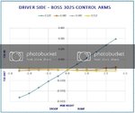
Below is a graph from Maximum Motorsports instructions to their Mm5TR-2 bump steer kit. The blue line represents the bump steer for a stock 2012 Mustang GT. The red line is the MM bump steer kit without any spacers and the correction to the stock bump steer is significant for this example 2012 Mustang GT. There is going to be some variability in the results from car to car, but the overall trend should be similar.

MM%20Bumpsteer%20Curve_2012%20GT.jpg

Based on the above graph, it looks like bump steer on the stock suspension can be significantly improved by installing a bump steer kit without any spacers. Using a bump steer gauge and dialing in the optimum spacer sizes will minimize the overall bump steer.

Because the Boss 302 shares the same Ford part numbers for the front lower control arm assembly (control arm, ball joints & bushings, CR3Z-3078-D, CR3Z-3079-D) and tie rod ends (DR3Z-3A130-A) with the Mustang GT, Shelby GT500 and base Mustang V6, adding a bump steer kit to a stock Boss 302 will have similar results .

In August 2010 when the new Boss 302 was announced, the features listed on the Boss 302 Hero Card indicated the Boss would be getting firmer suspension bushings on all four corners. Evidently the specs changed prior to the car going into production because the 2012 Mustang front control arm part numbers are the same for the 2011 & 2010 Mustang.

2012_boss_302_fact_sheet-page-002.jpg
 
Cherno134, thanks for posting this additional info its been very helpful.

So out of curiosity, on your setup do you have the .480 & .450 spacers in the bottom position of the Bump Steer kit and all remaining spacers occupying the top? Or, did you have a bunch of spacers left over that were not needed once you arrived at the ideal bottom stack height?

My thought is that your only to use what is needed to achieve the ideal setting in either Top or Bottom locations and anything left just gets filed away for future use.
 
The 0.450 & 0.480 spacers in my setup are on the top. They are between the spindle lug bottom and the top of the tie rod ends.

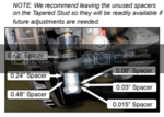
The left over spacers are on the bottom, between the bottom the tie rod end and end of the tapered stud bolt. This is their storage location. See the "Note" at the end of step #13 in the Maximum Motorsports instructions. ;)

Bump%20Steer%20Spacers.png
 
OK Folks,

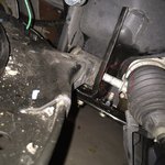
Things are starting to get interesting as I dive into this FLCA replacement. Anyone have any trade secrets they care to share on how to get this $&?@ing bolt out without removing the steering rack? I have one more trick up my sleeve to try but I'm not very optimistic that it will work. Some say that they have been able to remove this bolt by fully cranking the steering wheel to full lock in one direction or the other while pulling on the bolt. Thus far, by using only my hands to manipulate the steering arm and boot while working the bolt its not looking good :mad:

I've ran out of choice words to say about the Ford engineer who thought putting this bolt in the direct path of the steering arm was a good idea. In doing so they made an otherwise simple replacement into a real PITA.

One cheater approach that came to mind If the steering rack does indeed need to be unbolted was to grind off the tac welds that permanently secure the two nuts to the K-Member which the steering rack bolts passthru. If one were to take this approach it looks like they could then just unbolt the nuts from the easy to access lower location. After the job was complete, they could then just torque them back down again. I haven't decided just how bad an idea this would be yet because I suspect the reason they are tac'd in the first place is to prevent them from creeping out over time due to vibration.

While doing a dry run of attempting to remove the steering rack bolts from the top location I found that working room is at a premium and the angle is not ideal. The bolts are also said to be torqued to 85lb/ft and most likely have loc-tight of some flavour on them. :eek:

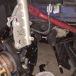
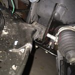
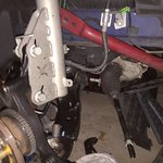
Here's a few pics of what I'm talking about and thanks in advance for any insight or short cuts you can provide:

17347786886_2606f74f17_b.jpg

16751214124_c34163a1d3_b.jpg
 

ArizonaBOSS

Because racecar.
Moderator
8,730
2,734
Arizona, USA
Sorry to say it but you are going to have to either remove the steering rack in-car, or drop the whole K-Member. I was told that it is very difficult to get to all the bolts for the rack with everything in-car; after seeing them come out (with the K off the car) with a real beating from an air impact, I can see why that is said. They have a ton of loctite and you will probably need heat if trying in-car.

Dropping the K sounded intimidating but it wasn't very difficult and was faster than expected.

I am in the middle of doing this as well, FLCAs are going back onto the car this weekend.

I thought maybe to remove the inner tie rods but apparently they are one-time use. It's not hard to drop the K; support the engine at the front of the transmission with a jack and wood block. Helpful to have a friend help as well.
 
2013dibgt said:
OK Folks,

Things are starting to get interesting as I dive into this FLCA replacement. Anyone have any trade secrets they care to share on how to get this $&?@ing bolt out without removing the steering rack? I have one more trick up my sleeve to try but I'm not very optimistic that it will work. Some say that they have been able to remove this bolt by fully cranking the steering wheel to full lock in one direction or the other while pulling on the bolt. Thus far, by using only my hands to manipulate the steering arm and boot while working the bolt its not looking good :mad:

I've ran out of choice words to say about the Ford engineer who thought putting this bolt in the direct path of the steering arm was a good idea. In doing so they made an otherwise simple replacement into a real PITA.

One cheater approach that came to mind If the steering rack does indeed need to be unbolted was to grind off the tac welds that permanently secure the two nuts to the K-Member which the steering rack bolts passthru. If one were to take this approach it looks like they could then just unbolt the nuts from the easy to access lower location. After the job was complete, they could then just torque them back down again. I haven't decided just how bad an idea this would be yet because I suspect the reason they are tac'd in the first place is to prevent them from creeping out over time due to vibration.

While doing a dry run of attempting to remove the steering rack bolts from the top location I found that working room is at a premium and the angle is not ideal. The bolts are also said to be torqued to 85lb/ft and most likely have loc-tight of some flavour on them. :eek:

Here's a few pics of what I'm talking about and thanks in advance for any insight or short cuts you can provide:

17347786886_2606f74f17_b.jpg

16751214124_c34163a1d3_b.jpg

I replaced the Steering Rack and the FLCA's without dropping the K-Member. It took a lot of patience and tools. Just finished changing out the Headers. This time I dropped the K-Member. Not difficult and much better approach for the rack or FCLA's.
 
Thanks for the info guys....

Yes the K-Member removal process does indeed scare the heck out of me only due to the lack of available extra hands during the process. It's just me. I've got about 10" of ground clearance at the moment which I suspect I would need to increase by at least another 5" or so to even make an attempt at the K removal. How much clearance did you require?

What are your thoughts on grinding off the welds on the two lower nuts that are secured to the K-Member used by the steering rack? Then unbolting them from the bottom? Do you recall if the bolts that feed thru the rack from the top are threaded the entire length or are they just threaded on the ends where the nuts are found? I guess these nuts could always be tac'd or Red Loc-Tighted back in place afterwards. Bad idea all around or not?

Thanks again.
 

ArizonaBOSS

Because racecar.
Moderator
8,730
2,734
Arizona, USA
There is a third bolt for the steering rack, you'll have to get all 3 of em.

The blue one plus the two silver ones.

10454964_10100805966643384_3820836045400944080_o.jpg


I THINK the only engagement is at the welded nuts, they just pass through the rack locations. IMO you will spend a lot of time grinding that shiznit vs. just dropping the K. Biggest deal will be getting a jack under the K so you can move it in/out of the car. Can you jack the car up higher? I think I have 10-12" clearance in the air.
 
Dropping the K-Member is the way to go - you'll be happy when you do - removing the rack and the FLCA is cake with the k-member out of the car. The idea of dropping the K-member sounds intimidating, but in practice is is much easier than you would think. Just follow the procedures in the shop manual.

I have removed the k-member twice so far without any other helping hands. I support the car with jack stands at the front pinch weld jacking points. My jack stands are adjusted up with the pin in the first hole. The top of the stands are 16 inches off the floor. I support the transmission at the bell housing with a scissor style transmission jack from Harbor Freight that has the castors removed. I place my floor jack pad at the k-member weight balance point by using a short piece of 2x4 under the two K-member "arms". After all the bolts, steering shaft, electrical connectors & tie rod ends are removed the K-member is lowered with the floor jack. Do it all in reverse to re-install.

The picture below is the set-up I used the first time. I was concerned about supporting the front of the engine and built a wooded cradle. The cradle got in the way when I lowered the K-member so I carefully removed and found it was NOT NEEDED with the transmission supported at the bell housing.

20140818_170759_1.jpg

20140818_195638.jpg
 
I did it without removing the K-member or steering rack.

You have to full lock so the rod is fully retracted on the side you want to work.
Then remove the small clip on the boot.
Then compress the boot as much as you can against the rack, lift the rod and pull the bolt out.

Also if the rear location of the arm is loose you can move it just enough to give you a little bit more space.

It won't come out easy but it will come out.
 

TMO Supporting Vendors

Buy TMO Apparel

Buy TMO Apparel
Top