Just finished up installing the AIM MXL2. I’ve been waiting for this unit to come on the market for some time, and in searching the web, found that Peter Krause is a distributor who had early units in stock. I hadn't heard of Peter prior to December, but having dealt with him, I highly recommend him to anyone looking for AIM gear (more on this later): www.peterkrause.net
I ordered the MXL2, GPS unit, CAN Data Hub and SmartyCam HD and 4 patch cables to tie in to my Autometer Elite gauges, together with the long Data cables for both the GPS and SmartyCam:
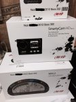
Peter configured the MXL2 to my specs, including Autometer gage data output calibration, specific to each of my gauges, threshold warning points for Diff temp, oil temp, Oil Pressure and Coolant, RPM shift thresholds, and Mustang ECU CAN calibration and track GPS data for all my favorite tracks, at no cost!
Step 1 was to up load the configuration data from the MXL2 to AIM’s PC management software RS3. This requires an external 12 volt feed to the MXL2 and a USB cable. RS3 allows you to view and modify the configuration data. Everything looked good, so I moved on to the physical install.
Step 2 is to remove the Steering Wheel. If you have the stock wheel, you need to ensure that the clock spring position is maintained. I have the Sparco/Ford Racing Wheel, so no worries there. Then remove the upper shroud – remove the two screws underneath the lower shroud then rotate the rear of the upper shroud upwards, with the column lowered to its lowest position
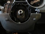
I got the mounting plate from Watson. Assume this is for the original AIM device:
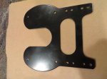
It required a liitle modification for the MXL2 and the Sparco wheel mounting hub:
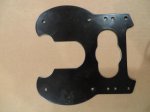
I then drilled small pilot holes in the lower upper and lowershroud to secure the mounting plate with self tapping screws. Photo below shows self tapping screws in lower shroud with upper shroud removed for wiring loom installation:

The wiring loom has adequate length connections for the CAN bus, 12 volt switched feed and USB connection. Extension patch cables are needed for any gage data outputs. The Can Data Bus has it’s own short extension cable which just reaches the center stack under the CD player:
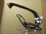
With the steering column still fully lowered take the wiring loom and install from the top of the column:
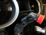
Then reinstall upper shroud:
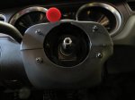
Next install the mounting plate. I used 4 self tapping screws. If you have the Sparco wheel, the hub has to be re-installed next (the flange sits behind the lower side of the MXL2). Finally install the MXL2 to the mounting plate:
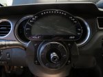
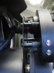
To provide clearance to the Sparco wheel hub, I used ½” spacers between the mounting plate and the MXL2 mounts:
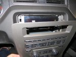
Next remove the top of the center consul and the HVAC/Audio panel:
I then removed the Audio control module (this is optional, my car is used mainly on the track, I have no need of audio and it provides more space for the gauge/ AIM hub wiring):
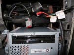
There are 3 connectors on the rear of the Audio module, the antenna cable has no securing tab, but is very tight:
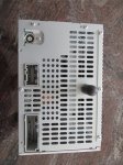
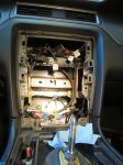
The center stack with the ACM removed:
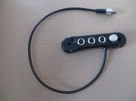
The CAN Bus data hub has a cable with a screw connector that connects to the MXL2 wiring loom:
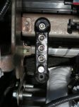
I mounted the data hub to the IP frame behind the location of the Audio control module:
Next I connected the Autometer gauge data output leads (Yellow/Black - GND) to the AIM patch cables (White/Black -GND) for Oil Pressure, Oil Temperature, Coolant Temp (center IP):
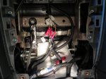
and Diff Temp (A-Pillar).
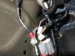
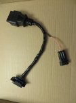
The ground connection can also be seen in the photo above. I tied the 12 volt switched power feed into the same feed used for the Autometer gauges. For the CAN bus connection, rather than splice into the main harness, I made up a short patch cable, and un clipped the original OBD 2 port:
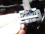
I then inserted the patch cable, an secured the end on the new cable in the original location (CAN+ is pin 6, CAN- is pin 14, GND is pin 5):
Next I moved on to install the GPS sensor:
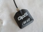
It has a magnetic base, do I made up a steel plate and tapped it to attach to a Maglite spring clip to attach to the rear Roll bar:
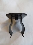
Then mounted the spring clip and GPS:
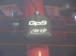
Installed the SmartyCam on the Roll Bar:
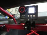
Zip tied the SmartyCam and GPS cables to the Roll Bar, removed the LH door sill plate and ran the cables under the carpet to the front wheel well:
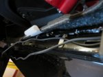
Then under the IP to the data hub in the center stack.
With the install complete, it was time to test. Fired up and no RPM readout, everything else OK. After an hour or so of diagnosis, I figured out that there was a bug in the AIM 2011 Mustang ECU configuration file! I guess I must have been the first 2011+ Mustang install. Both Peter and AIM were awesome – they had a bug fix to me in less than 1 Business day.
All set now:
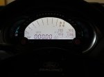
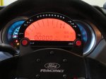
One last observation. Removing the Audio Control Module results in this in the display:
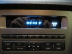
Still trying to figure out the pin out config, so I can ditch the HVAC panel without the blower defaulting to full on……..
I ordered the MXL2, GPS unit, CAN Data Hub and SmartyCam HD and 4 patch cables to tie in to my Autometer Elite gauges, together with the long Data cables for both the GPS and SmartyCam:

Peter configured the MXL2 to my specs, including Autometer gage data output calibration, specific to each of my gauges, threshold warning points for Diff temp, oil temp, Oil Pressure and Coolant, RPM shift thresholds, and Mustang ECU CAN calibration and track GPS data for all my favorite tracks, at no cost!
Step 1 was to up load the configuration data from the MXL2 to AIM’s PC management software RS3. This requires an external 12 volt feed to the MXL2 and a USB cable. RS3 allows you to view and modify the configuration data. Everything looked good, so I moved on to the physical install.
Step 2 is to remove the Steering Wheel. If you have the stock wheel, you need to ensure that the clock spring position is maintained. I have the Sparco/Ford Racing Wheel, so no worries there. Then remove the upper shroud – remove the two screws underneath the lower shroud then rotate the rear of the upper shroud upwards, with the column lowered to its lowest position

I got the mounting plate from Watson. Assume this is for the original AIM device:

It required a liitle modification for the MXL2 and the Sparco wheel mounting hub:

I then drilled small pilot holes in the lower upper and lowershroud to secure the mounting plate with self tapping screws. Photo below shows self tapping screws in lower shroud with upper shroud removed for wiring loom installation:

The wiring loom has adequate length connections for the CAN bus, 12 volt switched feed and USB connection. Extension patch cables are needed for any gage data outputs. The Can Data Bus has it’s own short extension cable which just reaches the center stack under the CD player:

With the steering column still fully lowered take the wiring loom and install from the top of the column:

Then reinstall upper shroud:

Next install the mounting plate. I used 4 self tapping screws. If you have the Sparco wheel, the hub has to be re-installed next (the flange sits behind the lower side of the MXL2). Finally install the MXL2 to the mounting plate:

To provide clearance to the Sparco wheel hub, I used ½” spacers between the mounting plate and the MXL2 mounts:

Next remove the top of the center consul and the HVAC/Audio panel:

I then removed the Audio control module (this is optional, my car is used mainly on the track, I have no need of audio and it provides more space for the gauge/ AIM hub wiring):

There are 3 connectors on the rear of the Audio module, the antenna cable has no securing tab, but is very tight:

The center stack with the ACM removed:

The CAN Bus data hub has a cable with a screw connector that connects to the MXL2 wiring loom:

I mounted the data hub to the IP frame behind the location of the Audio control module:

Next I connected the Autometer gauge data output leads (Yellow/Black - GND) to the AIM patch cables (White/Black -GND) for Oil Pressure, Oil Temperature, Coolant Temp (center IP):

and Diff Temp (A-Pillar).

The ground connection can also be seen in the photo above. I tied the 12 volt switched power feed into the same feed used for the Autometer gauges. For the CAN bus connection, rather than splice into the main harness, I made up a short patch cable, and un clipped the original OBD 2 port:

I then inserted the patch cable, an secured the end on the new cable in the original location (CAN+ is pin 6, CAN- is pin 14, GND is pin 5):

Next I moved on to install the GPS sensor:

It has a magnetic base, do I made up a steel plate and tapped it to attach to a Maglite spring clip to attach to the rear Roll bar:

Then mounted the spring clip and GPS:

Installed the SmartyCam on the Roll Bar:

Zip tied the SmartyCam and GPS cables to the Roll Bar, removed the LH door sill plate and ran the cables under the carpet to the front wheel well:

Then under the IP to the data hub in the center stack.
With the install complete, it was time to test. Fired up and no RPM readout, everything else OK. After an hour or so of diagnosis, I figured out that there was a bug in the AIM 2011 Mustang ECU configuration file! I guess I must have been the first 2011+ Mustang install. Both Peter and AIM were awesome – they had a bug fix to me in less than 1 Business day.
All set now:


One last observation. Removing the Audio Control Module results in this in the display:

Still trying to figure out the pin out config, so I can ditch the HVAC panel without the blower defaulting to full on……..
Last edited:

