The Mustang Forum for Track & Racing Enthusiasts

Taking your Mustang to an open track/HPDE event for the first time? Do you race competitively? This forum is for you! Log in to remove most ads.

  • Welcome to the Ford Mustang forum built for owners of the Mustang GT350, BOSS 302, GT500, and all other S550, S197, SN95, Fox Body and older Mustangs set up for open track days, road racing, and/or autocross. Join our forum, interact with others, share your build, and help us strengthen this community!
A6D72E3D-3058-486B-9A3E-B811871E1C76.jpeg

S197 Badger - 2011 S197 Gen3 Swap Build Thread Profile - S197 Mustangs

S197 Gen3 swap

This site may earn a commission from merchant affiliate links, including eBay, Amazon, and others.

Yesterday was an exciting one.
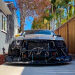
After months of waiting I finally received a big batch of Ohio based parts on a pallet and can finally commence assembly.
View attachment 97317
View attachment 97316
There is a long long lead time an any major cortex parts right now. They might say otherwise, but expect at least half a year to be safe so you don't get yourself caught in scheduling issues.

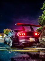
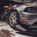
That said, their parts are gorgeous, what a delight to have those parts at hand now and I cant wait to test them out on track.


I went with this one:
Spal Electric Fans IX-30102049

Wow did this week took a turn.
Story time. Before I moved to the Gen3 I had forum member Andrew Weidemann work on my Gen1. The request was to add cams and springs and refresh the motor for good measures, timing chains and pumps.
After that it never ran properly again, kept throwing p0014 and other codes and could not be tuned. In short, he moved to a different state, effectively leaving the problem on my table to sort and pay and eventually claimed not to be responsible anymore.

Well heck, so I took the covers off this weekend to get an idea what is wrong with it. Keep in mind that this was an original Gen1 long block from 2010 that has never been opened or tampered with, aside from adding a larger oil pan and oil cooler. I never had any issues with it, never left me stranded and ran like a little old champ and to its last day was one of the fastest s197s in SoCal.

Discovery
The p0014 code indicated a possible issue with the timing. But the chains and timing checked out. Rear chains were spot on and the front chain was off by 4, but evenly. Not perfect but no real issue here. Okay good, but why the codes?
I noticed a whole bunch of sticker gunk on the chain guides which led me to check the oil pan and the pick up tube.

Oil Pick-up tube
This is what I found. It looks like a mix of baffle plastic, stickers and paint. Who knows what got sucked down further.
The gunk in the pick-up tube was certainly limiting the oil flow, which explains the p0014 cam timing code as the phasers will receive inconstant oil pressure and not actuate correctly.
For reference and a good watch in general: "Coyote Cam Phasers, how they work"

View attachment 84512
View attachment 84524
I see big plastic chunks, small plastic shreds, blue paint and a whole lot of other stuff which appears to be stickers and white paint.
View attachment 84523


Oil Baffle Debris
The oil baffle was cut by the builder to make swapping the oil pump easier. I know for a fact that debris dropped into the pan that he had to fish out. I was told this would not be an issue, the plastic will be crushed, burned up and I could flush it just in case. I did a lot of flushing but it looks like some bigger pieces did not come out of the baffles pan and ended up blocking the pick-up tube.
View attachment 84520View attachment 84521

Stickers
The real head scratcher are the stickers though. Why anyone would leave them on is beyond me. Low effort, high risk. The residue where the stickers used to be is still clearly visible.
View attachment 84532View attachment 84533View attachment 84538
Using a stethoscope camera I found even more stuff behind the chain guides.
View attachment 84534

For reference, this is how these guides usually come. One can only guess how much sticker material went through the block, oil, phasers and filters.
View attachment 84539View attachment 84541


Paint Chunks
Paint that has been used to mark cam and chains gotten loose, made it to the oil pan as well as the pick-up tube filter.
View attachment 84535View attachment 84536
More plastic debris in the oil pan.
View attachment 84545


Other Annoyances
Found the balancer like this. It was hammered on with a piece of wood. I was told that is easier and a good way. Did this cause the chips in the balancer? I don't know but it looks plausible.
View attachment 84547

Scratched head. No idea, could have been Ford.
View attachment 84546

Radiator fan was not hooked up, leading the car to overheat right away when bleeding the coolant.
View attachment 84544


What now?
1. Is this state acceptable for a $7500 cam and spring upgrade and oil, water pump and timing refresh?
2. What possible other effects could the gunked up pick-up tube have caused?
wow...just wow.
 
Little heads up as it's not in the manual and I found this to be causing some confusion and broken zerk fittings amongst SLA owners.

The zerk fittings on the SLA UCSs are meant for install and occasional maintenance only, as Cortex clarified and should be removed right after applying grease.
View attachment 97344

Don't leave them on as they might snap off.
Luckily they don't need a lot of maintenance so this is pretty much a non-issue.
Yup, found that out the hard way. Both front zerks are snapped off....the rear clear fine so no issue there.
 
Thats the right stuff there...are you running the race rear sway bar with this? What spring rates did you get?
Not yet but coming. Sway bar and Torque arm are at powder coating right now. Just waiting for them to be delivered.
Got to check on the rear but front is 1000lbs right now.
 
Not yet but coming. Sway bar and Torque arm are at powder coating right now. Just waiting for them to be delivered.
Got to check on the rear but front is 1000lbs right now.
Oh you Dog...that's my setup. They used to come with 850's ;)
 
I am going with what Filip suggests as a base line. But I am also totally not taking notes and absolutely not copying your setup as a starting point. Would never do that.
LOL, you are welcome to. That's what we do here, we share.
I'm happy to give you all my setup info and when you find your personal happy spot you can share that with me and others and everybody goes faster.
This is effing TMO here, we are brothers in the sport, sultans of speed, masters of Mustang and checkers collectors!
That is the way!
 
Back to the electronics and wrapping up test wiring for the main CAN

Over the last week I went step by step through all modules, added them to the CAN network and exposed them in the AIM data logger.
Everything is running on the same CAN as the Gen3 Control Pack ECU. All elements can be accessed and debugged via a single OBD2 port. Pretty slick in hindsight.


ABS
  • Connected to CAN
  • Wheel speed is reading
  • ABS bleed is working

Steering Rack
  • Connected to CAN
  • Angle data is reading

RCM
  • Connected to CAN
  • Doing its thing I guess.


How does it work?

They all just work together without issues as long as all wiring and grounding is done correctly.

This might or might not be possible with 3rd party ECUs. Try at your own risk.

RCM, ABS and Steering rack do not need the ECU and can all function in isolation.
Cross communication might be needed to function as expected. e.g. the ABS wants to see the brake pedal work, which is getting driven by the RCM

  • I found it vital to isolate each module and test each one on their own to rule out false negatives.
  • Keeping a constant eye on the CAN ohm level is essential.
    Depending on the setup resistors might have to be used but using resistors does not automatically assure it will work and adding additional modulus might mess with the ohm value. For instance I had to remove the resistor at some point to restore functionality.
  • This is a great video that helped me a lot understanding what ohm the CAN system expects:
 
Recreating the stock lighting was a great exercise to get familiar with the PDM32.
Not needed on track but it touches a lot of systems that need to work together: Channels, RIO2/Extensions, Power, Icons, Display, Keypad

It looks gloriously unspectacular but is a bit of work. Overall its is a great area to test and mess up as we are only dealing with low voltage lights.

Sequential Signal Lights
Signal_.gif

Solid Brake Lights incl. 3rd light
Brake_.gif

Sequential Hazard Lights
Hazard_.gif

Running Lights when low or high beams are active.
Running_.gif


I used a diode dynamics module for the sequencing of the signal lights and bypassed it with some diodes to retain proper brake lights:
IMG_7224.JPEG
  • Yellow to Yellow, Red and White with Diode Dynamics Modul
    This is the sequential modul.
  • Orange to Yellow, Red and White (individual)
    This is for brake lights.
    In order to work as proper brake lights they have to be bypassed with a 1-way diode (Schottky) each. Diode orientation is important here. If the current can cross over the brake lights will show as sequential.
  • Blue is the running Light
  • Black is Ground
 
Recreating the stock lighting was a great exercise to get familiar with the PDM32.
Not needed on track but it touches a lot of systems that need to work together: Channels, RIO2/Extensions, Power, Icons, Display, Keypad

It looks gloriously unspectacular but is a bit of work. Overall its is a great area to test and mess up as we are only dealing with low voltage lights.

Sequential Signal Lights
View attachment 97588

Solid Brake Lights incl. 3rd light
View attachment 97589

Sequential Hazard Lights
View attachment 97587

Running Lights when low or high beams are active.
View attachment 97590


I used a diode dynamics module for the sequencing of the signal lights and bypassed it with some diodes to retain proper brake lights:
View attachment 97591
  • Yellow to Yellow, Red and White with Diode Dynamics Modul
    This is the sequential modul.
  • Orange to Yellow, Red and White (individual)
    This is for brake lights.
    In order to work as proper brake lights they have to be bypassed with a 1-way diode (Schottky) each. Diode orientation is important here. If the current can cross over the brake lights will show as sequential.
  • Blue is the running Light
  • Black is Ground
Mine have sequential brake lights too....its absolutely beautiful and I get to show them to a lot of people on track, I don't want them to get bored.
 
You are such a ricer, smh 😁
For the longest time I retained my radio antenna….I got a kick out of people noticing it in the paddock like….wait, a radio antenna on a race car? This is a race car, right? lol.
 

TMO Supporting Vendors

Buy TMO Apparel

Buy TMO Apparel
Top