Hey everyone,
I am posting some tips on the installation of my Ford Racing/Autometer Performance information computer gauge #M-10898-CPIC (Autometer # 880089) in a Roush vent pod. This will apply to the ’12 Boss, and will most likely be the same for the ’13 (as well as any 10’-14 GT or V6). I recommend that you do this when you have plenty of free time and don’t rush it if this is your first time doing this.

PART 1
Removal of Dash Bezel
The first step is to remove the dash trim bezel so you can physically install the gauge and vent pod. It comes out pretty easily – just tilt the steering wheel all the way down (not as obvious as you would think) and then grab it by the back of the bezel where it meets the speedo/tach lenses and carefully but firmly pull it straight out. Make sure you didn’t lose any of the little white rubber feet (you can see one is missing on the left gauge opening that I found in the foot well later). Next you should remove the headlamp switch assembly so you can drop the wires through when you put the trim bezel with the gauge back in. You can take the trim bezel and work on it indoors in a comfortable place.

Removal of the Headlamp Switch Assembly
There is one 7MM bolt head screw on a bracket down below on the left (that I discovered after yanking on it for a while). Pop the bottom dash panel down all the way across on the driver’s side to reveal the screw and remove it. After the screw is out simply pry the assembly out a little with your fingernails carefully pull out and let it hang by the wires.

When you are done for now it will look like this.

Installing the Gauge and Pod in the Trim Bezel
Since Roush provided very good installation instructions for this I am just going to give you some additional tips.


This vent pod was a very clever idea by Roush and it is a quality piece, but the only thing I did not like about it is that you push the gauge in from the front and there is nothing holding it in from the back. The gauge could work itself loose through G-forces and someone could also pull the gauge out, snip the wires, and go (what can I say, I still think like a NYer). To remedy this I took the cylindrical back bracket provided by Autometer for securing the gauge and modified it to fit since it does not fit on the vent pod because it is angled and deep.

I cut the bracket with a little Stanley metal saw blade on a handle that I picked up from Home Depot. One side it cut shorter to stop against one side of the pod, and then the other side is cut longer to wedge in between the gauge and pod.


If I had to do it again I would have cut the long side parallel to either side of the embossment down the bottom to give me more length to reach down between the gauge and the pod (you can see it fell short). It is not going anywhere but I would have preferred a perfect fit, and I am not anal enough to do it over at this point.
Now the gauge is firmly secured in the pod.


After the gauge is in the pod you put it in the vent assembly and then put it back on the trim bezel.


Once the gauge and pod is assembled put it to the side, since the next step is Part 2 which is the fun part of running your 12V power wire over to the passenger foot well fuse box.
PART 2
Once the gauge and pod are assembled you put that aside and start on the wiring. For this gauge there are only three wires: red for 12V switched power, white to a dimming signal, and black to a good engine chassis ground. I highly recommend that you take the time and effort to wrap all wires in friction tape from end to end. There is a lot of metal bracketry that can cut into your wire and mess up your day. This is especially important for the red 12V power wire since it is a perilous journey from the gauge to the passenger foot well fuse box. The white and black just have a short trip below the gauge. I purchased just about everything I needed at Autozone.

AutoMeter has a helpful installation video on Youtube on a 2011 5.0 Mustang. It will also show you some of these tips plus others if you want to use an A-pillar pod or use other gauges that require senders.
http://www.youtube.com/watch?v=esdSIpgdQ1M
Running the 12V Power Wire
The 12V power wire is best tapped on the passenger foot well fuse box using an ATM Fuse Add-A-Circuit kit from Cooper-Bussmann (I work for Eaton/Cooper so I supported my employer in this mod). The gauge instructions recommend to wire a 1 Amp fuse in line with the gauge, so I bought an AGC fuse holder and some 1-amp fuses. I bought 30 feet of #16 gauge red stranded wire to run the power across. The FRPP gauge has #22 gauge leads. I dusted off my soldering skills and soldered the Add-A-Circuit to the fuse holder and then to the #16 wire.

Sorry I don’t have detailed pictures for this part but stopping to take pictures was slowing me down and I was running out of weekend. To run the power wire you start from the headlamp switch hole and go up on the right side of the vent and over and across the top of the gauge cluster and down the right side. I tucked the wire in the space above the gauge cluster and used 3/8” adjustable Kwik Klips with adhesive bases from Home Depot on either side of the gauge cluster to pull the wire taut. Before you go further drop the glove box door down by squeezing the sides in inward to get it past the stops, and open up the passenger foot well panel to expose the fuse box.

To continue the journey take the Add-A-Circuit end (leave enough slack to make it to the fuse box) and feed it over the top of the radio chassis and the glove box. This is where the friction tape helps because it stiffens the wire and gives you peace of mind that your wire will not get cut. Run the wire close to the front just above the display panel and you will make it across easily – as long as you don’t have stubby arms you can reach around through the glove box opening and catch the AAC as you feed it. You will see notches on the top of the radio chassis where you can tuck the wire behind. If you miss and the plug gets hooked on something behind the radio, jiggle it and patiently work it out. Do not yank on it otherwise you could damage the AAC.
Once you get it past the radio you will see two brackets above the glove box opening to feed it through. After you get to the right side of the glove box feed it close to the right wall and drop down into the passenger foot well. Be sure to double-check that the glove box closes and does not catch the wire. Take the extra time to use wire ties to keep everything in place around the glove box area. You are done here for now.
IMPORTANT! – DO NOT CONNECT THE AAC TO THE FUSE BOX AT THIS TIME. YOU NEED TO CONNECT THE WHITE WIRE AND BLACK WIRE FIRST!
Re-installing the Trim Bezel
With the 12V wire run you can now re-install the trim bezel with the gauge. I put the 3 wires together and wrapped them in friction tape from the back of the gauge down to headlamp switch opening. Take the wires from the gauge and drop them down through the opening. There is a gutter-type thing to the left of the vent – as you put the bezel in place reach behind and slide the wires up into the gutter so they do not get pinched when you push the vent in place. One the bezel is in position where you feel the clips are lined up in the holes, push it firmly in place and it pops right in.


Running and Connecting the Ground Wire
The black ground wire must be connected to a good engine chassis ground. AutoMeter recommend a place on the steering wheel bracket, but I did not want to create a warranty issue. Someone else pointed out a bolt on the dash mounting bracket next to the headlamp switch, but I found a better place which was an unused hole further in on the bracket. You can see that this bracket it connected to the metal of body so it is an excellent ground.

A ¼” bolt fits through the hole nicely so I bought a #14 stranded ground wire with ¼” lug, a hex head machine screw, a star lock washer, and a hex nut. I tried some other connectors and hardware at first that did not work well but I found that this was the right tool for the job. I bought the stuff from McMaster-Carr since our Home Depot has a crappy hardware selection these days.


Running and Connecting the Dimming Wire
There was much confusion about the white dimming wire. I found out after the fact that this gauge does not have back lighting or continuous dimming, so the purple wire with white stripe on the headlamp switch is not the one to splice into. The gauge LEDs dim to 50% when it sees 12V on the white wire, so you have to wire it to the parking lamp circuit instead, which AutoMeter tells me is a gray wire. I have to go back in and change this when I have a chance so I will post an update. The purple wire with white stripe is the correct one if your gauges have full range dimming capability. I used an 18-22 gauge quick splice connector. These can be a little tricky to use so be sure the wires are centered in the connector before you crimp it. I think people who I have read having trouble with these did not use the correct size.

Additional Thoughts
As I said, I highly recommend wrapping all wires in friction tape. You will see that the factory has done this as well.

Since all of your wires will be black when they are wrapped in friction tape, it is a good idea to leave a tiny bit of wire exposed in a safe place so you can identify the wires.

After all of this is done you are ready to connect the Add-A-Circuit to the fuse box and power the gauge up for the first time, which will be Part 3.
I am posting some tips on the installation of my Ford Racing/Autometer Performance information computer gauge #M-10898-CPIC (Autometer # 880089) in a Roush vent pod. This will apply to the ’12 Boss, and will most likely be the same for the ’13 (as well as any 10’-14 GT or V6). I recommend that you do this when you have plenty of free time and don’t rush it if this is your first time doing this.
PART 1
Removal of Dash Bezel
The first step is to remove the dash trim bezel so you can physically install the gauge and vent pod. It comes out pretty easily – just tilt the steering wheel all the way down (not as obvious as you would think) and then grab it by the back of the bezel where it meets the speedo/tach lenses and carefully but firmly pull it straight out. Make sure you didn’t lose any of the little white rubber feet (you can see one is missing on the left gauge opening that I found in the foot well later). Next you should remove the headlamp switch assembly so you can drop the wires through when you put the trim bezel with the gauge back in. You can take the trim bezel and work on it indoors in a comfortable place.

Removal of the Headlamp Switch Assembly
There is one 7MM bolt head screw on a bracket down below on the left (that I discovered after yanking on it for a while). Pop the bottom dash panel down all the way across on the driver’s side to reveal the screw and remove it. After the screw is out simply pry the assembly out a little with your fingernails carefully pull out and let it hang by the wires.
When you are done for now it will look like this.
Installing the Gauge and Pod in the Trim Bezel
Since Roush provided very good installation instructions for this I am just going to give you some additional tips.
This vent pod was a very clever idea by Roush and it is a quality piece, but the only thing I did not like about it is that you push the gauge in from the front and there is nothing holding it in from the back. The gauge could work itself loose through G-forces and someone could also pull the gauge out, snip the wires, and go (what can I say, I still think like a NYer). To remedy this I took the cylindrical back bracket provided by Autometer for securing the gauge and modified it to fit since it does not fit on the vent pod because it is angled and deep.
I cut the bracket with a little Stanley metal saw blade on a handle that I picked up from Home Depot. One side it cut shorter to stop against one side of the pod, and then the other side is cut longer to wedge in between the gauge and pod.

If I had to do it again I would have cut the long side parallel to either side of the embossment down the bottom to give me more length to reach down between the gauge and the pod (you can see it fell short). It is not going anywhere but I would have preferred a perfect fit, and I am not anal enough to do it over at this point.
Now the gauge is firmly secured in the pod.
After the gauge is in the pod you put it in the vent assembly and then put it back on the trim bezel.
Once the gauge and pod is assembled put it to the side, since the next step is Part 2 which is the fun part of running your 12V power wire over to the passenger foot well fuse box.
PART 2
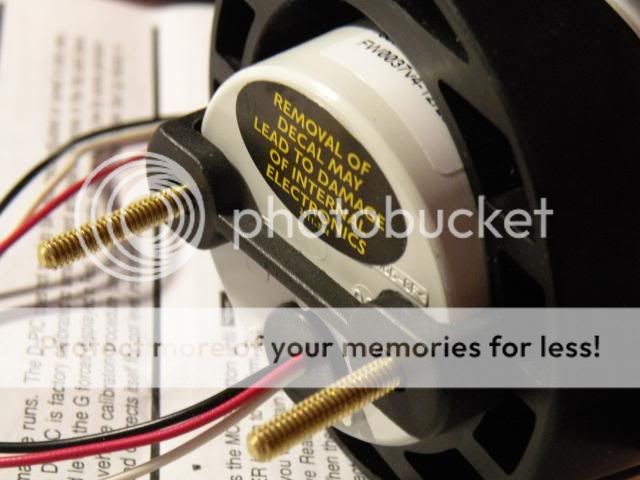
Once the gauge and pod are assembled you put that aside and start on the wiring. For this gauge there are only three wires: red for 12V switched power, white to a dimming signal, and black to a good engine chassis ground. I highly recommend that you take the time and effort to wrap all wires in friction tape from end to end. There is a lot of metal bracketry that can cut into your wire and mess up your day. This is especially important for the red 12V power wire since it is a perilous journey from the gauge to the passenger foot well fuse box. The white and black just have a short trip below the gauge. I purchased just about everything I needed at Autozone.
AutoMeter has a helpful installation video on Youtube on a 2011 5.0 Mustang. It will also show you some of these tips plus others if you want to use an A-pillar pod or use other gauges that require senders.
http://www.youtube.com/watch?v=esdSIpgdQ1M
Running the 12V Power Wire
The 12V power wire is best tapped on the passenger foot well fuse box using an ATM Fuse Add-A-Circuit kit from Cooper-Bussmann (I work for Eaton/Cooper so I supported my employer in this mod). The gauge instructions recommend to wire a 1 Amp fuse in line with the gauge, so I bought an AGC fuse holder and some 1-amp fuses. I bought 30 feet of #16 gauge red stranded wire to run the power across. The FRPP gauge has #22 gauge leads. I dusted off my soldering skills and soldered the Add-A-Circuit to the fuse holder and then to the #16 wire.
Sorry I don’t have detailed pictures for this part but stopping to take pictures was slowing me down and I was running out of weekend. To run the power wire you start from the headlamp switch hole and go up on the right side of the vent and over and across the top of the gauge cluster and down the right side. I tucked the wire in the space above the gauge cluster and used 3/8” adjustable Kwik Klips with adhesive bases from Home Depot on either side of the gauge cluster to pull the wire taut. Before you go further drop the glove box door down by squeezing the sides in inward to get it past the stops, and open up the passenger foot well panel to expose the fuse box.
To continue the journey take the Add-A-Circuit end (leave enough slack to make it to the fuse box) and feed it over the top of the radio chassis and the glove box. This is where the friction tape helps because it stiffens the wire and gives you peace of mind that your wire will not get cut. Run the wire close to the front just above the display panel and you will make it across easily – as long as you don’t have stubby arms you can reach around through the glove box opening and catch the AAC as you feed it. You will see notches on the top of the radio chassis where you can tuck the wire behind. If you miss and the plug gets hooked on something behind the radio, jiggle it and patiently work it out. Do not yank on it otherwise you could damage the AAC.
Once you get it past the radio you will see two brackets above the glove box opening to feed it through. After you get to the right side of the glove box feed it close to the right wall and drop down into the passenger foot well. Be sure to double-check that the glove box closes and does not catch the wire. Take the extra time to use wire ties to keep everything in place around the glove box area. You are done here for now.
IMPORTANT! – DO NOT CONNECT THE AAC TO THE FUSE BOX AT THIS TIME. YOU NEED TO CONNECT THE WHITE WIRE AND BLACK WIRE FIRST!
Re-installing the Trim Bezel
With the 12V wire run you can now re-install the trim bezel with the gauge. I put the 3 wires together and wrapped them in friction tape from the back of the gauge down to headlamp switch opening. Take the wires from the gauge and drop them down through the opening. There is a gutter-type thing to the left of the vent – as you put the bezel in place reach behind and slide the wires up into the gutter so they do not get pinched when you push the vent in place. One the bezel is in position where you feel the clips are lined up in the holes, push it firmly in place and it pops right in.
Running and Connecting the Ground Wire
The black ground wire must be connected to a good engine chassis ground. AutoMeter recommend a place on the steering wheel bracket, but I did not want to create a warranty issue. Someone else pointed out a bolt on the dash mounting bracket next to the headlamp switch, but I found a better place which was an unused hole further in on the bracket. You can see that this bracket it connected to the metal of body so it is an excellent ground.
A ¼” bolt fits through the hole nicely so I bought a #14 stranded ground wire with ¼” lug, a hex head machine screw, a star lock washer, and a hex nut. I tried some other connectors and hardware at first that did not work well but I found that this was the right tool for the job. I bought the stuff from McMaster-Carr since our Home Depot has a crappy hardware selection these days.
Running and Connecting the Dimming Wire
There was much confusion about the white dimming wire. I found out after the fact that this gauge does not have back lighting or continuous dimming, so the purple wire with white stripe on the headlamp switch is not the one to splice into. The gauge LEDs dim to 50% when it sees 12V on the white wire, so you have to wire it to the parking lamp circuit instead, which AutoMeter tells me is a gray wire. I have to go back in and change this when I have a chance so I will post an update. The purple wire with white stripe is the correct one if your gauges have full range dimming capability. I used an 18-22 gauge quick splice connector. These can be a little tricky to use so be sure the wires are centered in the connector before you crimp it. I think people who I have read having trouble with these did not use the correct size.
Additional Thoughts
As I said, I highly recommend wrapping all wires in friction tape. You will see that the factory has done this as well.
Since all of your wires will be black when they are wrapped in friction tape, it is a good idea to leave a tiny bit of wire exposed in a safe place so you can identify the wires.
After all of this is done you are ready to connect the Add-A-Circuit to the fuse box and power the gauge up for the first time, which will be Part 3.


